DC Electronic Loads
Programmable DC electronic loads sink controlled current, voltage, resistance, or power for testing power supplies, batteries, solar panels, fuel cells, and any DC source under realistic operating conditions. The UNI-T electronic load catalog covers the UTL1000S family at 200 W and 400 W power tiers in standard and high-resolution variants, with constant-current, constant-voltage, constant-resistance, and constant-power operating modes plus dynamic-load transient programming for power-supply transient response characterization and battery cycle testing. The real-time waveform display shows load behavior under transient events — uncommon at this price point and useful for diagnosing supply stability margins.

DC Electronic Loads
| Voltage | Current | Power | Resolution | Slew Rate | Frequency | Connectivity | |
|---|---|---|---|---|---|---|---|
|
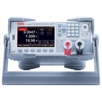
150V | 30A | 200W/400W | 0.01 mV/0.01mA | 0.0006 A/µs–3 A/µs | 50kHz | RS232 |
| UTL1000S Load Banks | |||||||
Buying Guide
UNI-T DC Electronic Load — Buyer's Guide
What Is a DC Electronic Load For?
A DC electronic load draws programmable current from a device under test, simulating the behavior of a real consumer of power — a motor stalling, an LED panel switching on, a battery discharging into a regulator, a power supply seeing its rated full-load current. It's how engineers characterize power sources — batteries, DC power supplies, solar panels, fuel cells, USB-PD chargers, switching regulators — without firing up the actual end-use load.
The choice comes down to power rating (how much energy the load can dissipate continuously) and measurement resolution (how precisely you can program and read the load current).
What Every UTL1000S Shares
Mode set, automation hooks, and safety features are identical across the line. You're choosing for power and resolution.
Decision 1: Choose Your Power Rating
Pick the smallest unit that exceeds the worst-case continuous draw of the source you're testing, with reasonable headroom. Pulse and dynamic-load testing can briefly exceed continuous rating; continuous discharge must stay within it.
UTL1020S / UTL1020S-E
UTL1040S / UTL1040S-E
Decision 2: Full Spec or Economy?
Within each power class, the standard model and the -E economy variant share identical modes, automation, and protections. They differ on current-readback resolution — the smallest current step the front panel and the SCPI interface can resolve.
| Model | Power | Current Resolution | When to choose |
|---|---|---|---|
| UTL1020S | 200 W | 0.01 mA / 0.1 mA | Standby-current measurement, leakage characterization, precision low-current battery testing |
| UTL1020S-E | 200 W | 0.1 mA / 1 mA | General load testing where 0.1 mA resolution is adequate — most bench work |
| UTL1040S | 400 W | 0.01 mA / 0.1 mA | Battery characterization on multi-cell packs where capacity at low loads matters |
| UTL1040S-E | 400 W | 0.1 mA / 1 mA | High-power bench loading where the full 400 W is needed but micro-amp resolution is not |
Rule of thumb: Pick the standard model (UTL1020S, UTL1040S) when your test plan includes standby, leakage, low-power-mode, or battery capacity at low draw. Pick the -E variant when your minimum measurement current is greater than 1 mA and you want the value-pick price point.
Applications the UTL1000S Series Covers
Battery characterization
Pick: UTL1020S for cells, UTL1040S for packs — constant-current or constant-power discharge to a programmable cutoff voltage, with cumulative Ah/Wh capacity logging. Use the 0.01 mA resolution of the standard models to capture self-discharge and standby current at the low end of the curve.
DC Power Supply validation
Pick by PSU rating — load-regulation testing, transient response, full-load thermal characterization, OCP/OVP/OPP verification. Use dynamic mode to simulate sudden load steps and watch the supply's recovery on a scope. Pairs cleanly with any UNI-T DC power supply as the source.
USB-PD and USB-C charger test
Pick: UTL1020S — 200 W headroom covers 100 W PD chargers with margin. List mode runs through the negotiated voltage profiles (5/9/15/20 V) with the load drawing rated current at each. Short-circuit mode validates the charger's overcurrent protection.
LED driver and lighting test
Pick: UTL1020S for most fixtures, UTL1040S for high-bay — constant-current mode simulates the LED string at its forward-voltage operating point. Pulse mode lets you measure dimming response on PWM-driven drivers.
Solar panel I-V curve sweep
Pick: UTL1040S — list mode steps load resistance across the panel's output curve to trace I-V characteristics, find the maximum power point, and validate microinverter MPPT algorithms against a real panel under varying irradiance.
Automotive 12 V / 24 V load simulation
Pick: UTL1040S — 400 W at low-voltage automotive bus levels supports starter motors, ECU loading, infotainment, and lighting circuit characterization. Dynamic mode reproduces engine-start current draw profiles.
ATE / production-line
Pick by power requirement, prefer -E variants for cost — the Handler interface provides hardware go/no-go signals to test station controllers. SCPI over RS-232 or USB lets the load take its setpoint from a sequencer script. Build a pass-fail station in under a day.
Education and lab teaching
Pick: UTL1020S-E — same mode set and front panel as the standard model at the entry-level price point. Students learn CC/CV/CR/CP behavior on real loads without breaking the lab budget.
Why Choose UTL1000S?
Four modes, real dynamic loading
CC, CV, CR, CP cover every load-simulation scenario. Dynamic mode runs the load as a programmable pulsed current with controlled rise, fall, and duty — not a steady-state-only instrument that can't represent real loads.
Battery test built-in
Capacity-in-Ah and energy-in-Wh logging are first-class features, not add-ons. Programmable discharge profiles with voltage-cutoff stop conditions match how production battery test plans actually run.
ATE-ready from day one
Handler interface plus SCPI over RS-232 and USB lets the load drop into existing test rigs without an interface adapter board. Start with one bench unit; scale to a production rack.
3+2 year warranty
Three-year base warranty, two additional years on registration. Parts, labor, return shipping included.
FAQ
Can the load handle short-duration pulses above its continuous rating?
Yes — short pulses can exceed continuous rating in dynamic mode, with rating curves derated for pulse width and duty cycle. The continuous power rating (200 W or 400 W) is the steady-state thermal limit; brief transients can go higher within the load's transient envelope.
What's the difference between CC and CR mode in practice?
Constant-current draws a fixed amperage regardless of source voltage — useful for testing a battery at a defined discharge rate. Constant-resistance simulates a real fixed load like a motor or LED string, where current scales with voltage. Pick CC for characterizing sources; CR for emulating end-loads.
Can I parallel two units for higher power?
Not natively as a master-slave pair — the UTL1000S series is designed as standalone instruments. If your test needs more than 400 W, the right path is to wait for a higher-power model in the series or step up to a different power class. We'll update this guide as additional models are released.
How do I integrate this with a UNI-T power supply for a full source/load setup?
The UTL1000S takes its setpoint over RS-232, USB, or front-panel. Pair it with any UNI-T DC power supply — typically the UDP5000 for programmable switching supplies or the UDP3000C/UDP4000S for linear bench work — and drive both from a single test script.
Why pick the -E variant over the standard?
Cost. The -E gives you the same mode set, the same dynamic and list capabilities, the same protections — at lower current-readback resolution. If you never measure below 1 mA, you don't pay for the resolution you wouldn't use.
Match the power to the load. Pick the -E if you don't need micro-amp resolution.

